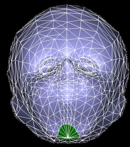
Metamorphosis of 3D Polyhedral Models Using Progressive Connectivity Transformations

Chao-Hung Lin and Tong-Yee Lee

Department of Computer Science and Information Engineering

National Cheng-Kung University, Tainan, Taiwan, R.O.C.

1        

Source Model

(#vertices/ #edges)

Target Model

(#vertices/ #edges)

Average no. of vertices for the intermediate meshes

2703 / 7881

2982 / 8607

2842


  A morphing between the models of a cow and a horse. (Demo 256*256)
2      

Source Model

(#vertices/ #edges)

Target Model

(#vertices/ #edges)

Average no. of vertices for the intermediate meshes 

2637 / 8229

2795 / 8979

 2716


  A morphing between the models of a triceratops and a pig. (Demo1 256*256), (Demo2 256*256)
3    

Source Model

(#vertices/ #edges)

Target Model

(#vertices/ #edges)

Average no. of vertices for the intermediate meshes 

1954 / 5856

50002 / 150000

 25978


  A morphing between the models of a man's head and a venus's head. (Demo1 256*256), (Demo2 1024*1024)
4    

Source Model

(#vertices/ #edges)

Target Model

(#vertices/ #edges)

Average no. of vertices for the intermediate meshes 

779 / 2328

1954 / 5856

 1465


   A morphing between the models of a clown’s head and a man’s head. (Demo 256*256)
5    

Source Model

(#vertices/ #edges)

Target Model

(#vertices/ #edges)

Average no. of vertices for the intermediate meshes 

44955/ 134859

50002 / 150000

 47478


  A morphing between the models of a man's head and a venus's head.  

(Demo1 256*256), (Demo2 1024*1024), (Demo3 1024*1024)

6

Input Model 1

(#vertices/ #edges)

Input Model 2

(#vertices/ #edges)

Input Model 3

(#vertices/ #edges)  

Average no. of vertices for the intermediate meshes 

319/ 951

313/ 937

 329/981

 321


  Shape transition between three dolphins with different poses. (Demo1 256*256) ,(Demo2 256*256)
7      
  A transition between two 2D embeddings. (Demo 256*256). These two embeddings correspond to the portions of two models in purple color.

Demonstrate how the popping effects are reduced using our strategies.

 Vertex Matching Priority Control Function
A1.  No No Demo
A2.  Yes No Demo
A3.  Yes Demo
A4.  Yes Demo

In the proposed paper, the following strategies are used to reduce the popping effects. 1) Vertex matching is performed to decrease the number of executions of three primitive operations.2) To appropriately schedule three primitive operations. In this table, we demonstrate how the popping effects are reduced using these two strategies. 

In the example A1, we do not execute the RoughVertexMatching() procedure and do not use the priority control function. We can see a serious popping effect in the demo.

In the example A2, the RoughVertexMatching() procedure is performed. We can see a great deal of  popping effects are reduced in comparison with A1.

In the examples A3 and A4, the  RoughVertexMatching() procedure is performed and  two different priority control functions are used. We can see the popping effects are reduced further.

Note that in both examples A1 and A2, we do not use priority control functions. In these two cases, we equally divides the equal  number of edges and vertices into N groups and assign each group one by one  among N frames. In our design, the user can interactively modify the curves of these functions to find  appropriate priority control curves. If we can choose appropriate priority control functions, we can get better results. For example, as we interactively choose curves as shown in A3 and A4, we find A3 and A4 are better than A1 and A2 (i.e., less popping effect). And A4 is slightly better than A3. Therefore, we think priority control function is a good tool to control morphing and to reduce popping effects.